Difference between revisions of "Raspberry Pi Serial"
| Line 10: | Line 10: | ||
== Overview == |
== Overview == |
||
The RPI_SERIAL board breaks out two SPI busses, the UART and the I2C bus of the BCM2835 SOC on the raspberry pi. |
|||
== Assembly instructions == |
|||
=== Possible Configurations === |
=== Possible Configurations === |
||
The board can be configured for EITHER 3.3V or 5V. This is done by moving a solder-jumper. See [[solder jumpers]] for how to move a solder jumper. |
|||
In contrast to the expansion boards that have a "default" setting for the solder jumper by having a small trace between two of the pads, the RPI_SERIAL boards have been designed to FORCE us to think about what option we want by not providing any default. |
|||
== External resources == |
|||
If you remove the solder jumper and forget to put it back on in the other position (or if you fail to make the contact), the power led will not light. |
|||
== Pinout == |
|||
The 28 pin gpio connector is described at elinux: [[http://elinux.org/RPi_Low-level_peripherals]] |
|||
The SPI connector has the same pinout as the atmel 6-pin ICSP connector and is documented here: [[SPI_connector_pinout]]. |
|||
== Additional software == |
|||
The I2C connector is documented here: [[I2C_connector_pinout]]. |
|||
=== Related projects === |
|||
== Pinout == |
|||
=== LEDs === |
=== LEDs === |
||
There is one power led. (the current version of the board has "R5" silkscreened next to the footprint where we thing the led should be. We'll swap the led and resistor in the future.) |
|||
== Jumper settings == |
== Jumper settings == |
||
none (or see above for "configuration options"). |
|||
== Programming == |
== Programming == |
||
None. |
|||
== The software == |
|||
== Default operation == |
|||
== Future hardware enhancements == |
|||
== Future software enhancements == |
|||
== Changelog == |
|||
Revision as of 14:06, 29 May 2012
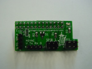
This is the documentation page for the Raspberry Pi Serial board.
The RPI_SERIAL board breaks out the serial busses on the raspberry pi. This allows the raspberry pi to communicate at 3.3V CMOS levels with say an arduino mini or other 3.3V asynchronous devices. But also the I2C bus and SPI busses are broken out. BitWizard has a bunch of expansion boards that can connect to those busses.
This page will say more about the hardware in the future, once things are tested. For now see Raspberry pi expansion system page
Overview
The RPI_SERIAL board breaks out two SPI busses, the UART and the I2C bus of the BCM2835 SOC on the raspberry pi.
Possible Configurations
The board can be configured for EITHER 3.3V or 5V. This is done by moving a solder-jumper. See solder jumpers for how to move a solder jumper.
In contrast to the expansion boards that have a "default" setting for the solder jumper by having a small trace between two of the pads, the RPI_SERIAL boards have been designed to FORCE us to think about what option we want by not providing any default.
If you remove the solder jumper and forget to put it back on in the other position (or if you fail to make the contact), the power led will not light.
Pinout
The 28 pin gpio connector is described at elinux: [[1]]
The SPI connector has the same pinout as the atmel 6-pin ICSP connector and is documented here: SPI_connector_pinout.
The I2C connector is documented here: I2C_connector_pinout.
LEDs
There is one power led. (the current version of the board has "R5" silkscreened next to the footprint where we thing the led should be. We'll swap the led and resistor in the future.)
Jumper settings
none (or see above for "configuration options").
Programming
None.
- Initial public release
