Difference between revisions of "Reducing power consumption of a raspberry Pi"
| Line 1: | Line 1: | ||
= Introduction = |
= Introduction = |
||
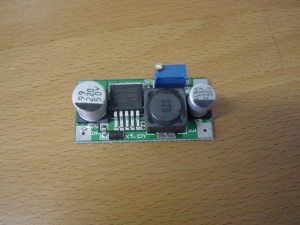
The Raspberry Pi relies on a linear regulator for its 3V3 rail. This dissipates a third of the energy as heat, which is a bit of a waste, if you want to power your Pi from an battery. Our solution: Replace the linear regulator with a [http://bitwizard.nl/shop/power-heat/dc-dc-step-down-conv switching regulator from our shop]. We also used another regulator for the 5V power, to test powering a Pi from a car battery. |
The Raspberry Pi relies on a linear regulator for its 3V3 rail. This dissipates a third of the energy as heat, which is a bit of a waste, if you want to power your Pi from an battery. Our solution: Replace the linear regulator with a [http://www.bitwizard.nl/shop/power-heat/dc-dc-step-down-conv switching regulator from our shop]. We also used another regulator for the 5V power, to test powering a Pi from a car battery. |
||
[[File:switcher.jpg|none|thumb|300px|alt=One of our switching regulators|One of our switching regulators]] |
[[File:switcher.jpg|none|thumb|300px|alt=One of our switching regulators|One of our switching regulators]] |
||
Latest revision as of 12:59, 18 August 2014
Introduction
The Raspberry Pi relies on a linear regulator for its 3V3 rail. This dissipates a third of the energy as heat, which is a bit of a waste, if you want to power your Pi from an battery. Our solution: Replace the linear regulator with a switching regulator from our shop. We also used another regulator for the 5V power, to test powering a Pi from a car battery.
Initial measurements
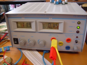
We tuned our benchtop power supply to 12V DC, and set the current-limit to approximately 400mA. Then we adjusted one of the switching regulators to 5V, and labelled it. We gave our Pi an SD card, and ethernet connection. We then hooked up the power to the Pi, on its GPIO header (GND on pin6, 5V on pin2). After booting, the current consumption from the benchtop supply stabilized between 190 and 200mA, which translates to a power consumption of about 2,4W.
Slicing the Pi
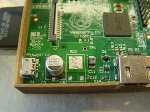
To make sure the linear regulator stopped wasting power, we completely removed it from our Pi, with a hot air rework station. To do this, we grip the regulator with some metal tweezers, lift the Pi about a centimetre, and then blast the regulator with air at about 400 degrees Celsius. After a few seconds, the Pi drops to the table, and the regulator was removed:
Decorating the Pi
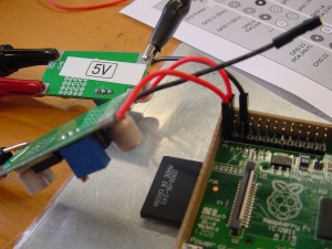
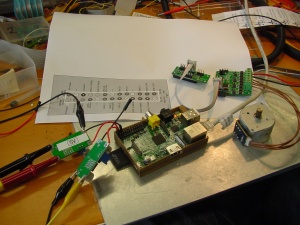
We adjusted a second switcher to 3,3V and connected both the 5V and 3V3 switchers to the GPIO header of the Pi (with the benchtop power supply still turned off); 3V3 on pin1, 5V on pin2, GND on pin6.
The Pi also got the same SD card and ethernet connection as with the initial measurements.
We double/triple checked everything, crossed our fingers, and turned on the benchtop supply. After booting, the power consumption settled on 150mA at 12V, a 25% improvement!
Further reduction
A further power reduction can be achieved by tying the 5V and 3V3 lines both to the 3.3V DCDC converter (and obviously removing the 5V one). Everything that depends on the 5V will stop working, but most of the 'pi will work. What won't work are devices depending on the 5V powersupply on the GPIO, HDMI and the USB connectors.
Conclusion
If you're not afraid of modifying your Raspberry Pi, and want to power it from a limited power source, such as a battery or solar panel, it's well worth the trouble and cost of replacing the linear regulator by a switching one. The only downside is that the extra regulator takes up a little extra room.
