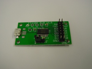
FT245RL V1.5
Revision as of 16:50, 6 November 2015 by Cartridge1987 (talk | contribs)
This is the documentation page for the FT245RL breakout board. That can be bought in the BitWizard shop.
Overview
The FT245RL breakout board has an USB connector, one 16-pin IO connector. The brains of the PCB, of course, is an FT245RL chip.
External resources
Pinout
The 16-pin connector is connected as follows:
| 5V | 3V3 |
| TXE# | RXF# |
| RD# | WR |
| D7 | D5 |
| D5 | D4 |
| D3 | D2 |
| D1 | D0 |
| GND | GND |
LEDS
- The only LED is a power LED
Jumper settings
The only jumper is for selecting the I/O voltage. Place the jumper on the left side for 3V3, or on the right side for 5V.
future hardware enhancements
Changelog
1.1
- Initial public release
